Quadcopter Modeling and Fail-Safe Flight Control

Low-cost dynamic modeling and fault-tolerant control that keep a quadcopter flying and landing after losing one, two, or even three motors

Gene Patrick S. Rible*, Nicolette Ann A. Arriola, Manuel C. Ramos Jr.
Electrical and Electronics Engineering Institute, University of the Philippines Diliman, Quezon City, Philippines
*Contact researchers: grible@vols.utk.edu

Best Presentation Award, ICCAR 2020

A DJI FlameWheel 450 stabilizing and landing on two opposing propellers after induced motor failure.

About this work

Stable flight normally needs at least four propellers, yet a quadcopter that loses a motor mid-air does not have to fall. This body of work, carried out at the Electrical and Electronics Engineering Institute of the University of the Philippines Diliman, shows how to keep one flying and land it safely after the complete loss of two opposing or three motors, using only its onboard sensors and processor.

The two papers build on each other. The first establishes a complete dynamic model of the quadcopter using alternative, low-cost methods: it recovers propeller thrust, torque, and speed relationships, and the airframe's rotational aerodynamic drag, without the expensive reaction-torque sensor such characterization usually requires. The second uses that model to design and test two fail-safe controller architectures (three-propeller and two-propeller) that detect a failure, identify which motors are gone, and stabilize the vehicle for a controlled return and landing. The fail-safe paper received the Best Presentation Award at the 2020 6th International Conference on Control, Automation and Robotics (ICCAR) in Singapore.
The papers

Fail-Safe Controller Architectures for Quadcopter with Motor Failures

Gene Patrick S. Rible, Nicolette Ann A. Arriola, Manuel C. Ramos Jr.

2020 6th Int'l Conf. on Control, Automation and Robotics (ICCAR), Singapore 2020  Best Presentation Award

A fail-safe algorithm that stabilizes and lands a quadcopter after the complete loss of two opposing or three motors. Both the three-propeller and two-propeller architectures pair an LQR inner attitude controller with a damped second-order outer controller, run entirely on the onboard processor, and were validated in simulation and on hardware.

Modeling and Implementation of Quadcopter Autonomous Flight Based on Alternative Methods to Determine Propeller Parameters

Gene Patrick S. Rible, Nicolette Ann A. Arriola, Manuel C. Ramos Jr.

Adv. Sci. Technol. Eng. Syst. J. 5(5) 727 2020

The modeling foundation for the fail-safe work. It recovers the quadcopter's propeller and airframe-drag parameters with only a scale and basic electrical measurements, no reaction-torque sensor, and shows that the resulting model behaves identically to the real vehicle in both simulation and flight. A practical baseline for small-scale researchers with limited equipment.

Highlights across this work

How it works and what we found

A quadcopter model anyone can build

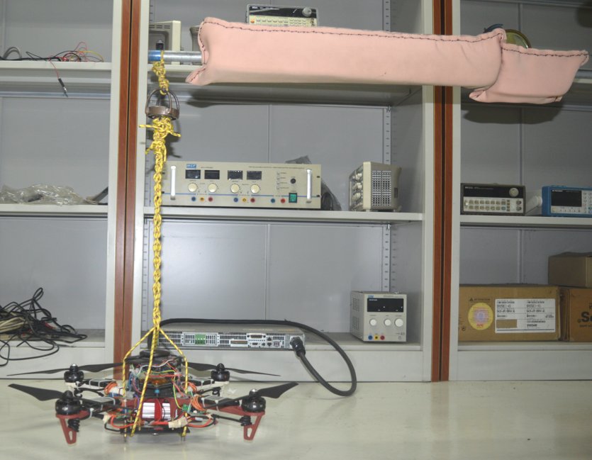
The quadcopter suspended on a vertical rope-and-bearing rig that lets it spin freely about its yaw axis to characterize airframe air resistance.

Rope-and-bearing rig for air-resistance characterization

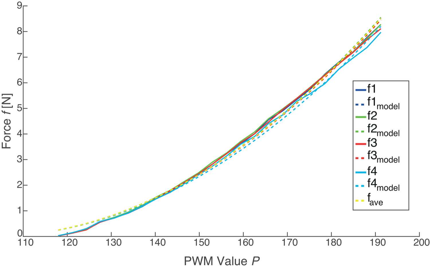
Propeller thrust as a function of PWM command value: measured data and the fitted model for all four propellers and their average.

Thrust vs PWM command

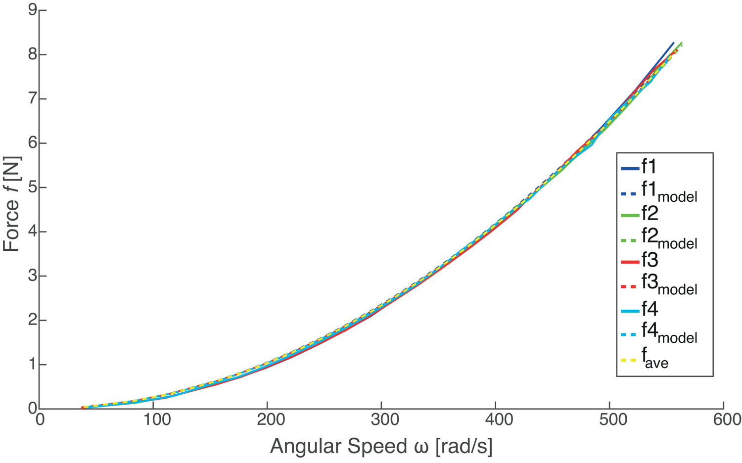
Propeller thrust as a function of propeller angular speed: measured data and the fitted model.

Thrust vs angular speed

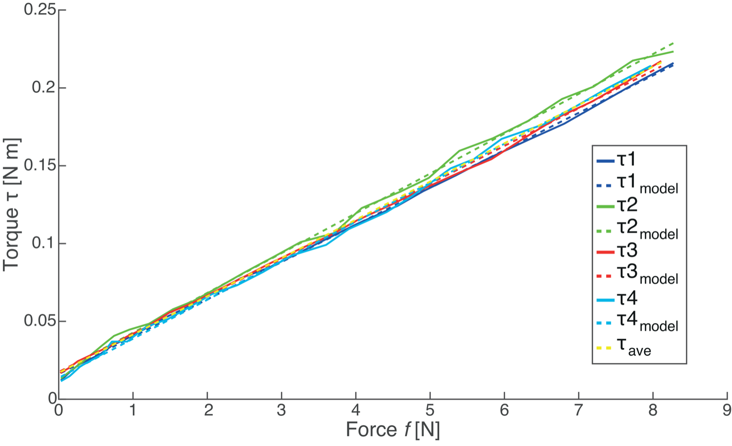
Reaction torque as a function of propeller thrust: measured data and the fitted model.

Reaction torque vs thrust

Propeller characterization from the journal paper. Solid lines are measurements; dashed lines are the fitted models averaged across the four propellers.

Accurate quadcopter control needs the relationships between motor command, propeller speed, thrust, and reaction torque, plus the airframe's moments of inertia and aerodynamic drag. These are normally measured with costly equipment such as a reaction-torque sensor. The journal paper replaces that with simple benchtop methods: a weighing scale and tachometer for thrust and speed, current and voltage readings for electrical torque, a pendulum swing for the moments of inertia, and a free-spinning rope-and-bearing rig for the body drag. Scaling motor commands to a finer internal range reduced thrust discretization by two orders of magnitude, giving noticeably smoother flight.

Validated in simulation and in the air

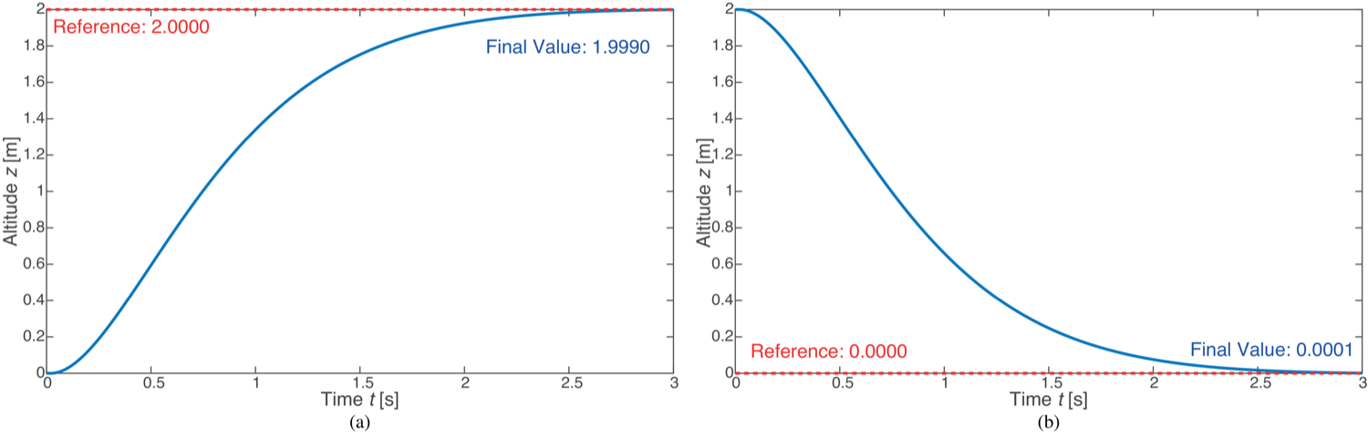
Simulated quadcopter altitude response: commanded ascent from 0 to 2 m, and controlled landing from 2 to 0 m, with attitude unaffected.

Simulated altitude response: ascent to 2 m and controlled landing

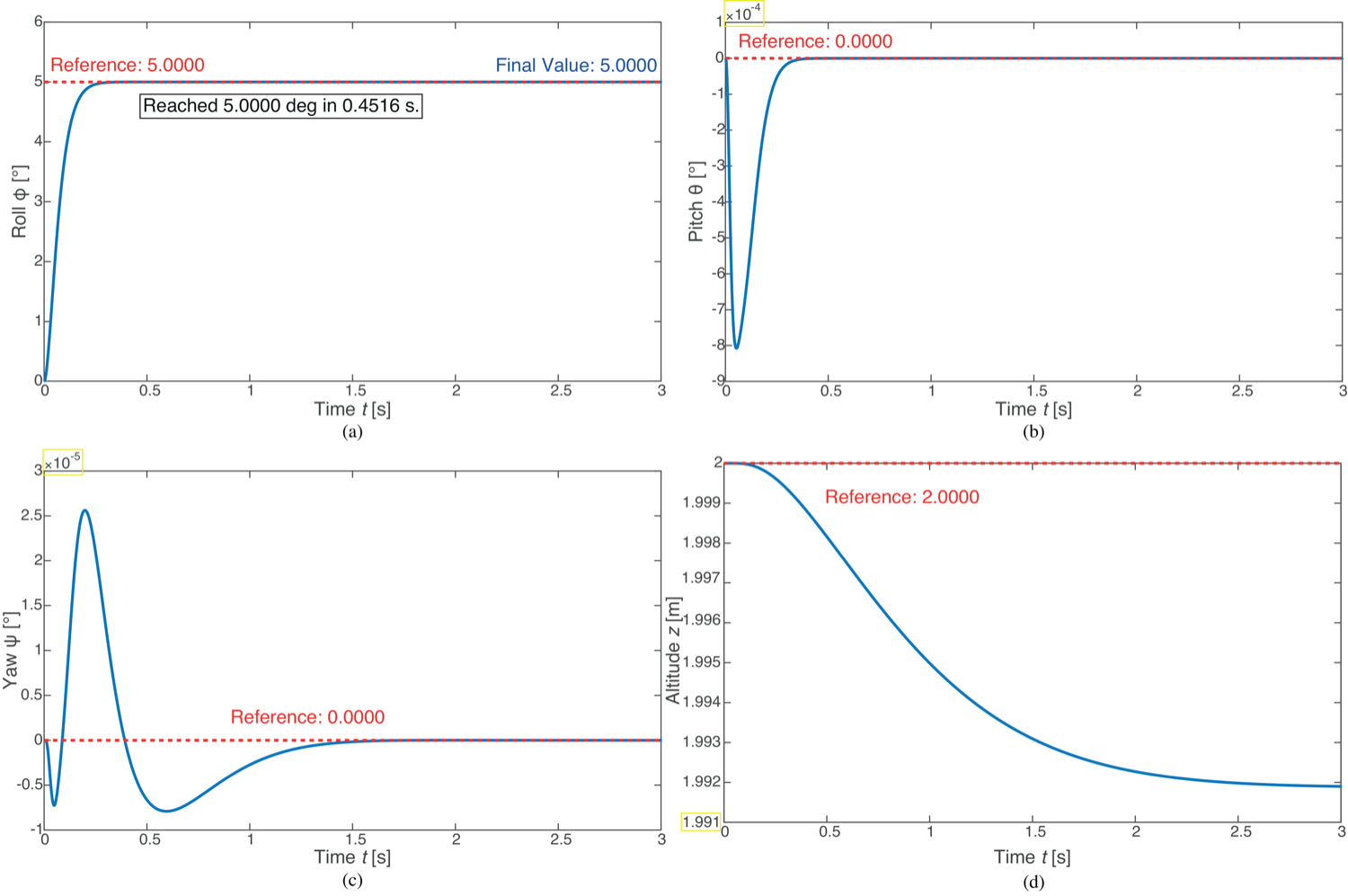
Simulated quadcopter response when banking from 0 to 5 degrees along the roll axis: roll reaches the command while pitch, yaw, and altitude stay essentially unchanged.

Simulated roll-banking response, with pitch, yaw, and altitude held steady

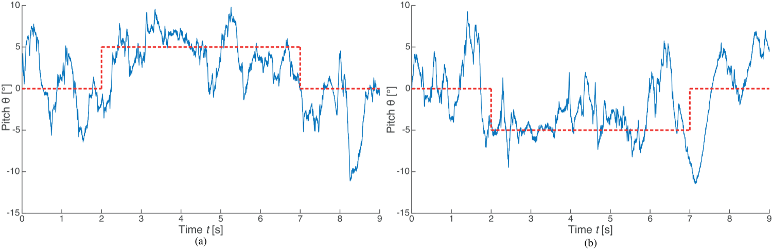
Implemented quadcopter pitch response to positive and negative banking commands.

Implemented pitch response to banking commands

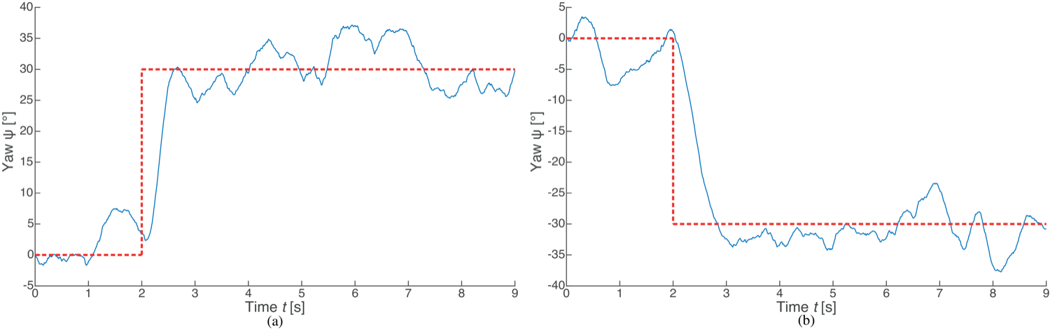
Implemented quadcopter yaw response to positive and negative rotation commands.

Implemented yaw response to rotation commands

The assembled model may not capture every true parameter value, yet because the reaction torque and drag enter the dynamics in the same way, the model behaves identically to the real quadcopter. A basic PID flight controller tuned on the model held altitude and tracked roll, pitch, and yaw commands in MATLAB simulation, then flew on the physical DJI FlameWheel 450 with matching behavior. That agreement is what makes the model trustworthy as the basis for the harder fail-safe problem.

Two ways to survive a dead motor

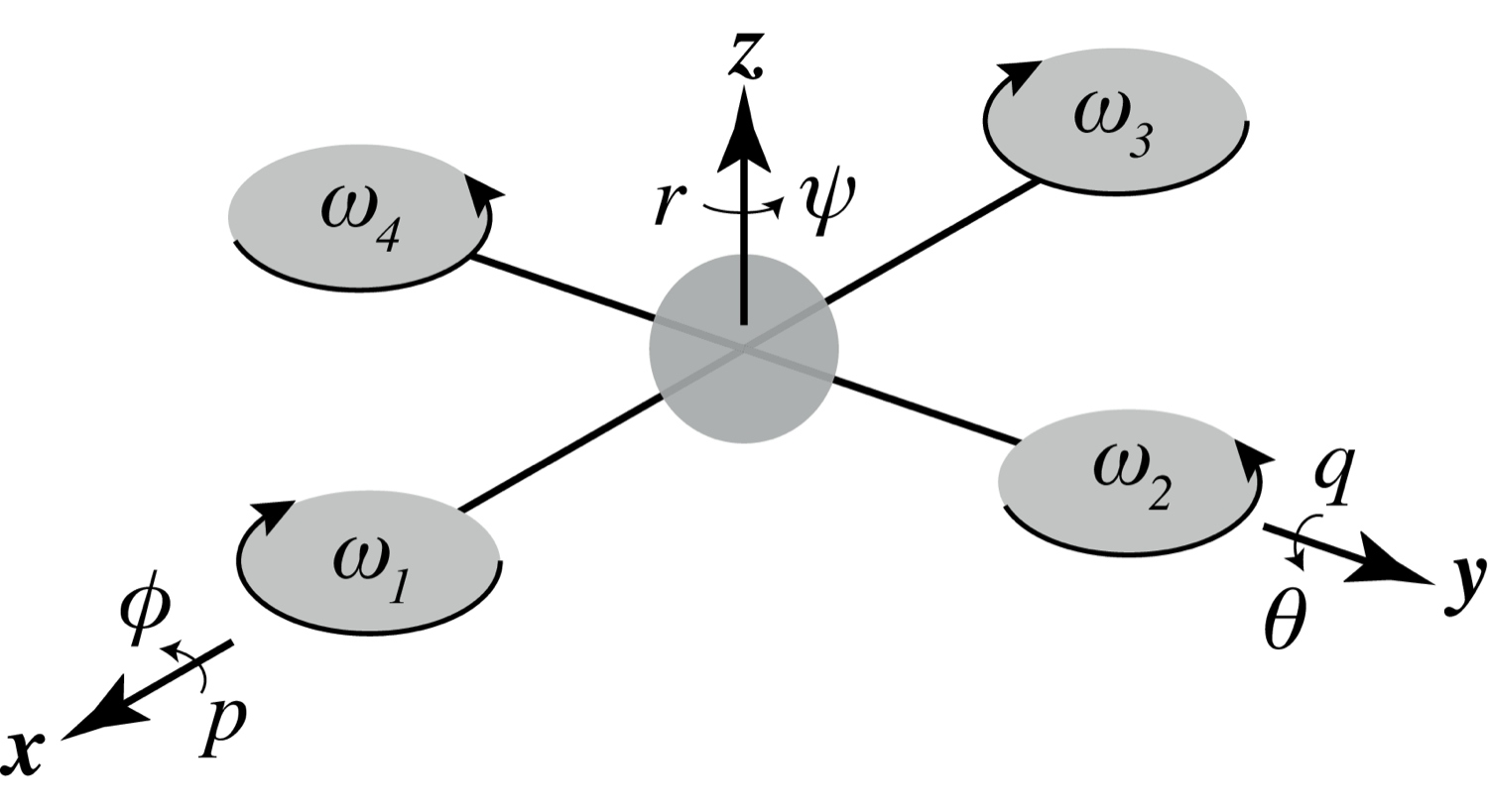
Quadcopter kinematic diagram: four propellers arranged symmetrically about the center of mass, with body axes x, y, z and the roll, pitch, and yaw rotations.

Quadcopter kinematic diagram and coordinate frame

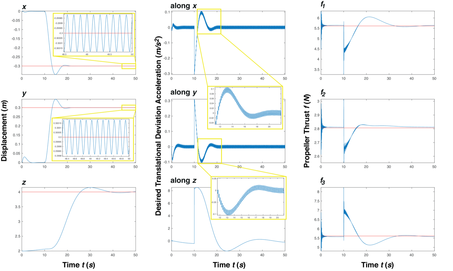
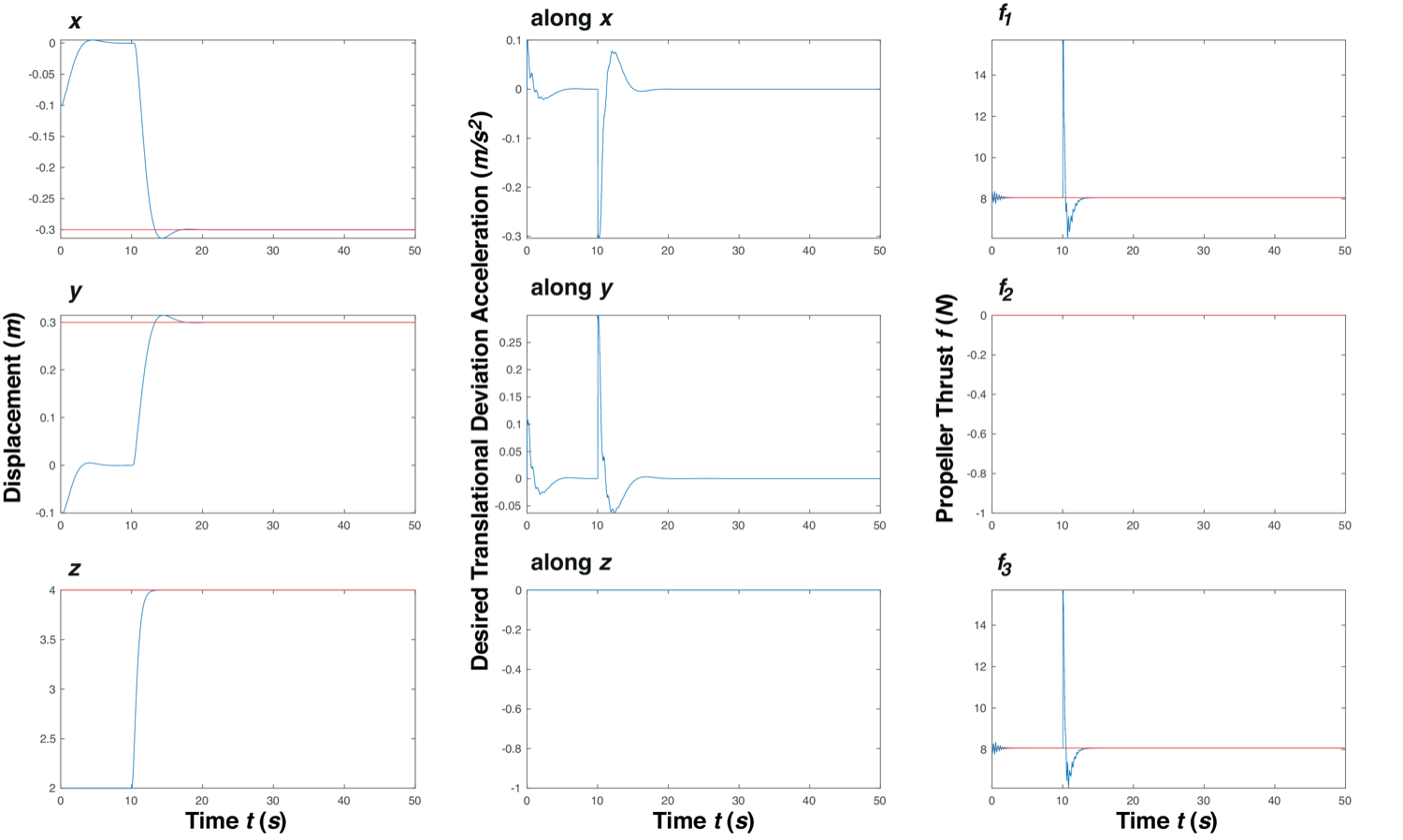
Simulated three-propeller response, part 1: translational coordinates, desired translational deviation acceleration, and the required propeller thrusts approaching equilibrium.

Three-propeller response: position and thrusts

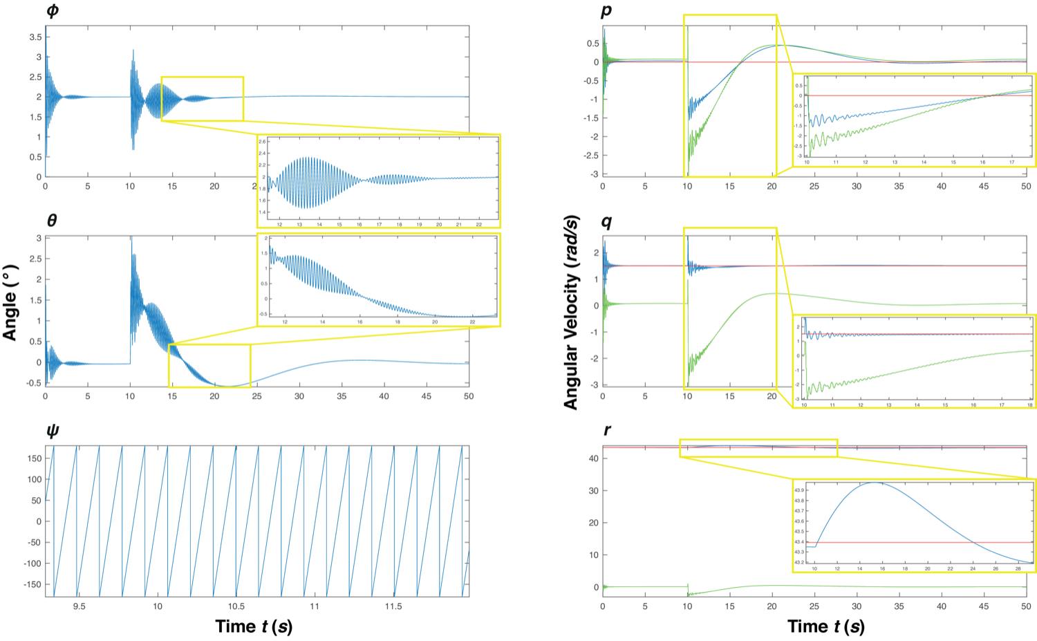
Simulated three-propeller response, part 2: roll, pitch, and yaw angles and the body-frame angular velocity components approaching steady state.

Three-propeller response: attitude and angular rates

Simulated two-propeller response, part 1: translational coordinates and required thrusts after a reference change.

Two-propeller simulated response: position and thrusts

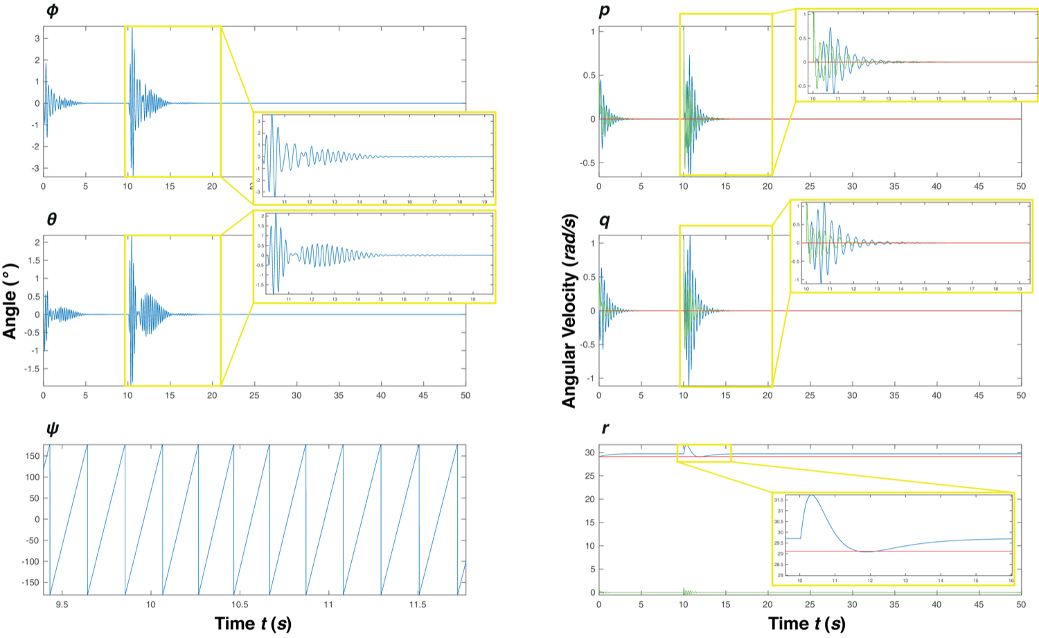
Simulated two-propeller response, part 2: attitude angles and body-frame angular velocities stabilizing about the primary spin axis.

Two-propeller simulated response: attitude and rates

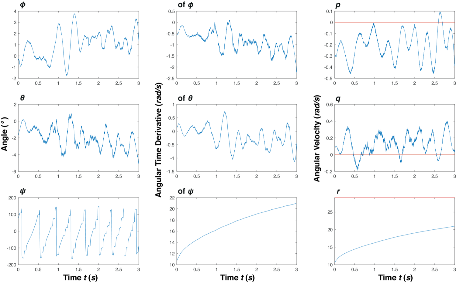
Implemented two-propeller attitude response while hovering: measured roll, pitch, yaw, their time derivatives, and body-frame angular velocity components stabilizing within bounds.

Implemented two-propeller attitude response while hovering on the physical quadcopter

When a motor fails, the quadcopter gives up control of one attitude direction and spins about a primary axis to stay aloft. Two architectures handle this. The three-propeller case augments the inner controller with a PID on propeller-force deviations and distributes thrust across the remaining motors, lowering the demand on each. The two-propeller case decouples altitude onto its own PID controller, separate from the LQR attitude loop, which makes it more efficient, more robust, and more stable. Both were tuned and tested, with the two-propeller controller stabilizing and hovering the physical quadcopter on a rope-and-bearing rig.

Detecting the failure, and why spin helps

Table II · Signature spikes of motor-failure combinations (ICCAR conference paper)
Motor failure p q r φ θ
1↑↓↑
2↓↑↓
3↓↓↓
4↑↑↑
1, 3↓
2, 4↑
2, 3, 4↓↑↓
1, 3, 4↑↓↑
1, 2, 4↑↑↑
1, 2, 3↓↓↓

↑ spikes upward, ↓ spikes downward, blank means no characteristic spike. Each failure case leaves a distinct pattern across the angular rates (p, q, r) and attitude angles (φ, θ).

Table V · Fail-safe controller initial-condition limits (ICCAR conference paper)
State variable Three-propeller Two-propeller
+ − + −
φ22.2°−16.2°109.7°−111.0°
θ20.0°−20.1°103.5°−104.0°
p19.9 rad/s−24.1 rad/s19.2 rad/s−18.9 rad/s
q16.2 rad/s−19.0 rad/s25.2 rad/s−25.5 rad/s
r212.7 rad/s−14.8 rad/s∞−6.6 rad/s
x∞−∞∞−∞
y∞−∞∞−∞
z∞−∞∞−∞
ẋ∞−∞∞−∞
ẏ∞−∞∞−∞
ż∞−0.5 m/s11.0 m/s−∞

The largest initial deviation each architecture can recover from. The two-propeller limits are far wider (it tolerates roll and pitch past ±90°). The highlighted yaw-rate limits on r are the binding constraints: the quadcopter must already be spinning fast enough about its primary axis.

Each combination of failed motors produces a distinct pattern of spikes across the angular rate and attitude readings, so the controller can identify which motors are gone from the IMU alone, with no extra sensors. Analysis of the output limits, initial-condition limits, and controller frequencies showed the two-propeller architecture tolerates far larger disturbances. A key finding: increasing the induced yaw rate unconditionally lowers the in-plane components that must be controlled, so faster spin yields greater stability. That also means larger, heavier vehicles or those with more air resistance are harder to recover.

Videos

The demonstration cited in the papers, and the award-winning ICCAR 2020 conference presentation.

Demonstration

The quadcopter stabilizing about its primary axis after induced motor failure, and the controller gains tuning process.

ICCAR 2020 presentation

The recorded conference talk that received the ICCAR 2020 Best Presentation Award.

Citations

@inproceedings{rible2020failsafe,
  author    = {Rible, Gene Patrick S. and Arriola, Nicolette Ann A. and Ramos, Jr., Manuel C.},
  title     = {Fail-Safe Controller Architectures for Quadcopter with Motor Failures},
  booktitle = {2020 6th International Conference on Control, Automation and Robotics (ICCAR)},
  address   = {Singapore},
  publisher = {IEEE},
  year      = {2020},
  doi       = {10.1109/ICCAR49639.2020.9108038}
}

@article{rible2020modeling,
  author  = {Rible, Gene Patrick S. and Arriola, Nicolette Ann A. and Ramos, Jr., Manuel C.},
  title   = {Modeling and Implementation of Quadcopter Autonomous Flight Based on Alternative Methods to Determine Propeller Parameters},
  journal = {Advances in Science, Technology and Engineering Systems Journal},
  volume  = {5},
  number  = {5},
  pages   = {727--741},
  year    = {2020},
  issn    = {2415-6698},
  doi     = {10.25046/aj050589}
}

Acknowledgments

This project was supported in part by grants from the UP Engineering Research and Development Foundation, Inc.

Discussion

Questions, comments, and follow-up work in the quadcopter and aerial-robotics community. Sign in with GitHub to post.