← Back to the anthology

Dynamic drop penetration of vertically oriented fiber arrays

An energy model for penetration depth; vertical hydrophilic arrays penetrate more than hydrophobic ones, opposite to horizontal fibers.

Gene Patrick S. Rible*, Visalsaya Chakpuang, Aidan D. Holihan, Hannah P. Sebek, Hannah H. Osman, Kyle R. Brown, Wei Wang, Andrew K. Dickerson
Department of Mechanical, Aerospace and Biomedical Engineering, University of Tennessee, Knoxville, Tennessee 37996, USA
*Contact researchers: grible@vols.utk.edu

Physics of Fluids 37, 022108 (2025)

Featured Article

Abstract

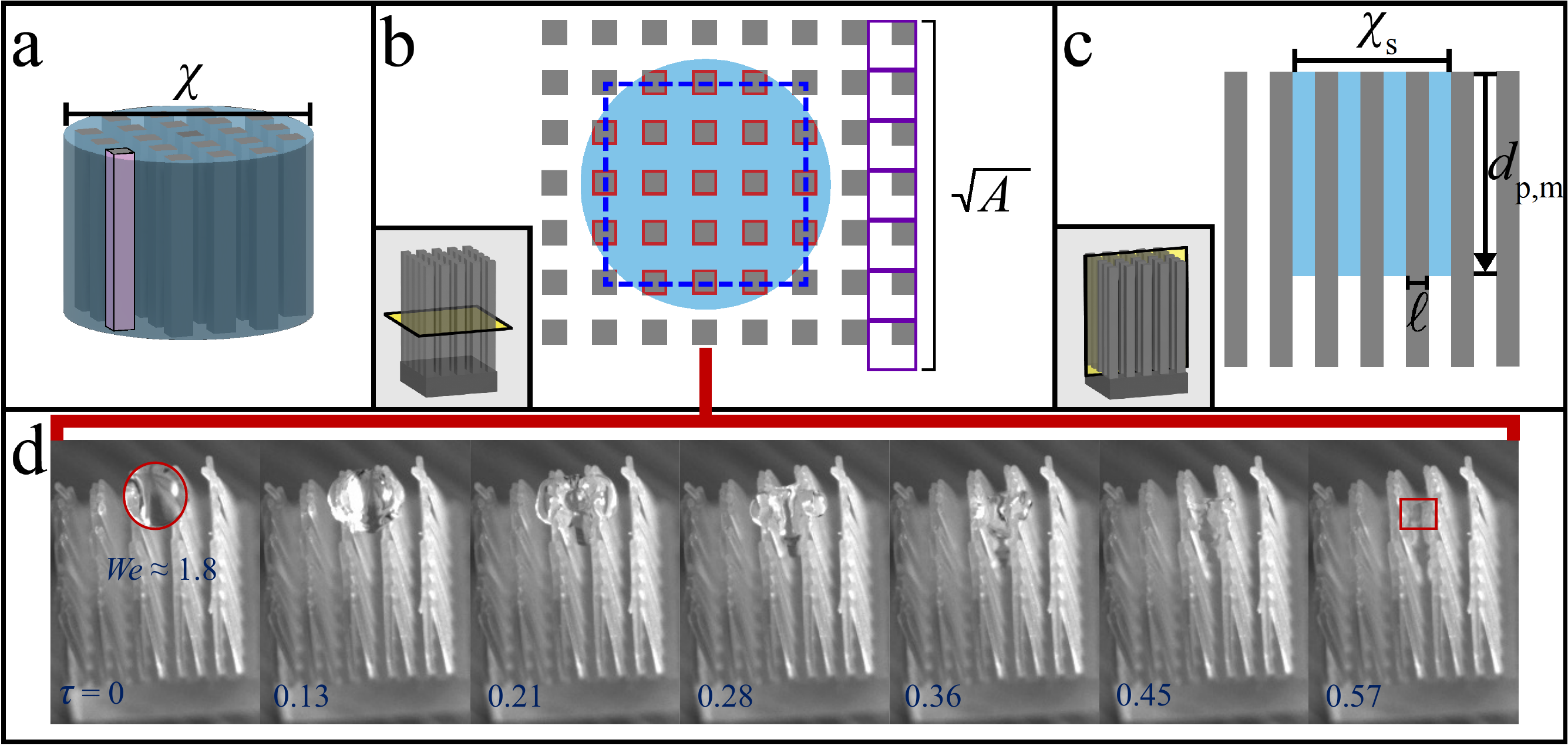
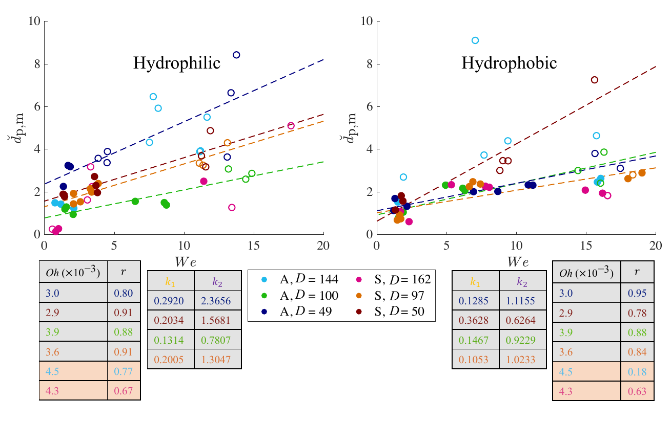
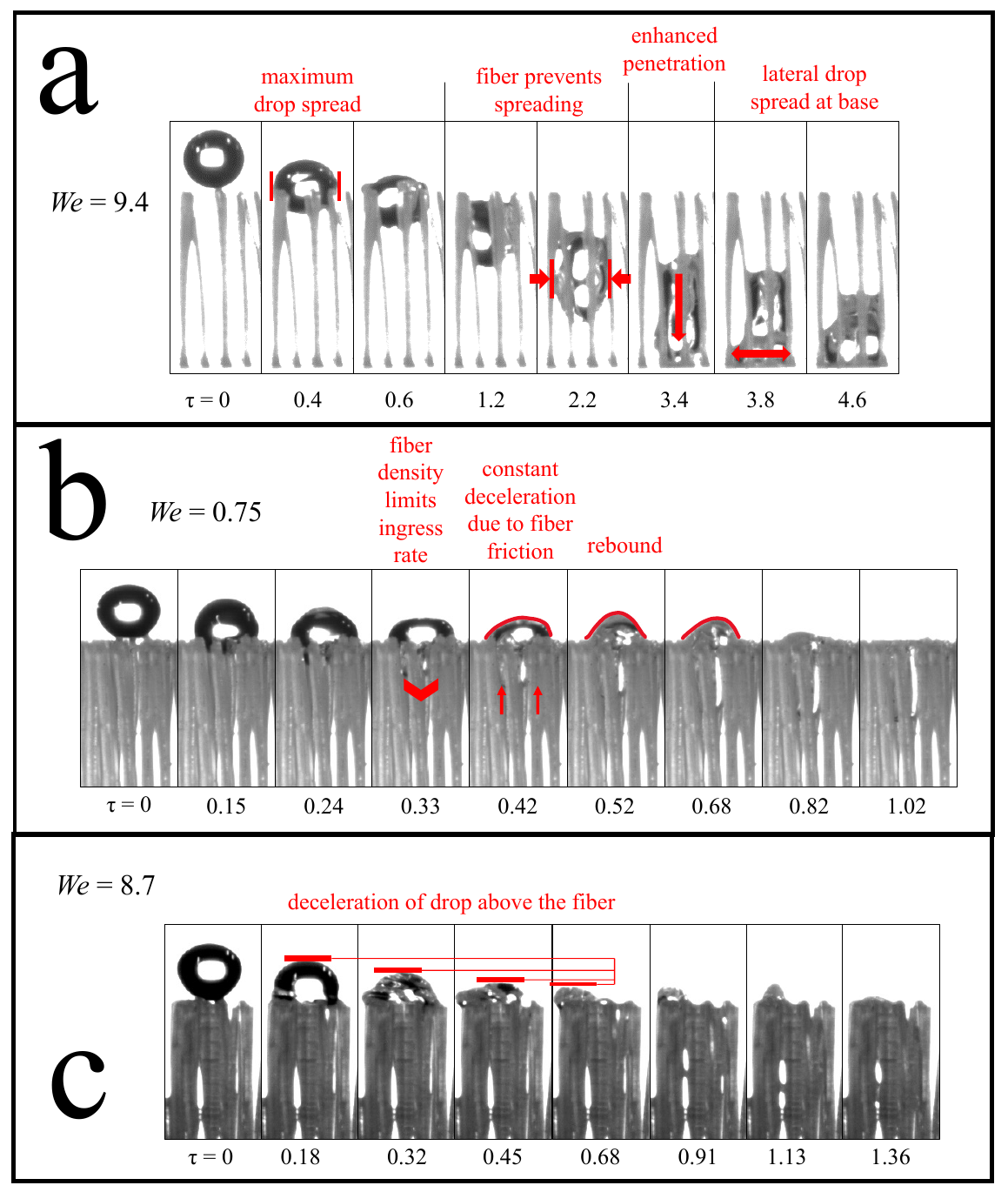
This experimental work investigates the impact dynamics of drops on vertically oriented, three-dimensional (3D)-printed fiber arrays with variations in packing density, fiber arrangement, and wettability. These fiber arrays are inspired by mammalian fur, and while not wholly representative of the entire morphological range of fur, they do reside within its spectrum. We define an aspect ratio, a modified aspect ratio relative to the drop size, that characterizes various impact regimes. Using energy conservation, we derive a model relating drop penetration depth in vertical fibers to the Weber number. In sparse fibers where the Ohnesorge number is less than 4 × 10⁻², penetration depth scales linearly with the impact Weber number. In hydrophobic fibers, density greatly reduces penetration depth when the contact angle is sufficiently high. Hydrophilic arrays have greater penetration than their hydrophobic counterparts due to capillarity, a result that contrasts with horizontal fibers. Vertical capillary infiltration of the penetrated liquid is observed whenever the Bond number is less than 0.11. For hydrophobic fibers, we predict higher density will produce complete drop penetration when the contact angle is sufficiently low. Complete infiltration by the drop is achieved at sufficient times regardless of drop impact velocity.

Firsts in this work

New experimental tools and observations from this paper.

How it works and what we found

Why vertical arrays behave differently

Movie 1: Eight impact classifications

Figure 5

Figure 5 from the paper: (a, b) Modified aspect ratio AR* vs Weber number for observed impact classifications, hydrophilic (left) and hydrophobic (right). Solid symbols mark impacts where the drop did not reach the bottom of the fiber array; symbols with a black outline mark impacts where the drop penetrated to the bottom. (c) Occurrence of drop rebound in the AR*-We spectrum in vertical fibers. (d) Theoretical maximum penetration depth predicted from a constant-deceleration model when the impacted drop reaches the base of the array.
Figure 1 from the paper: 3D-printed vertical fiber arrays. Cross-section of a strand, aligned vs staggered top-view configurations, hydrophobic and hydrophilic contact angles, and the D0/U/dp/chi dimensional impact parameters.
Figure 2 from the paper: illustration of trans-fiber motions. Normal, Wave, Bisection, and Wave plus Bisection. These lateral motions are unique to vertical arrays.

The drop now impacts fiber tips rather than fiber sides, so its kinetic energy converts to penetration through a different geometric channel. We tabulate the new impact regimes via a modified aspect ratio.

An energy-conservation model for penetration depth

Movie 2: Contact angles, apparent vs. actual

Movie 3: Maximum drop spread at fiber tips

Figure 7 from the paper: graphical accompaniment to the penetration-depth model. Cylindrical drop projection becoming a rectangular steady-state footprint inside the array, with the supporting area-projection image sequence at the bottom.

We balance kinetic energy at impact against the work done by drag and capillary forces on the descending liquid front. In the sparse regime (Oh < 4 × 10⁻²) the prediction is linear in We; experiments confirm.

Capillarity helps hydrophilic vertical arrays penetrate

Figure 8 from the paper: normalized maximum penetration depth versus Weber number, hydrophilic (left) and hydrophobic (right) panels with linear k1*We + k2 fits across multiple densities. Hydrophilic curves sit above hydrophobic at low We; the wettability inversion versus horizontal fibers.

In contrast to horizontal fibers, vertical hydrophilic arrays draw additional liquid downward via capillarity, deepening the wetted column.

A Bond-number criterion for capillary wicking

Whenever the Bond number of the residual drop falls below 0.11, the trapped liquid wicks vertically along the fibers, extending the effective penetration depth beyond what impact alone would predict.

Liquid penetration decelerates at a constant rate

Movie 4: Constant deceleration of liquid front

Movie 5: Drop deceleration above the array

Figure 6 from the paper: image sequences of drops impacting vertical arrays at We = 9.4 (max spread plus lateral spread at base), We = 0.75 (low-We rebound plus capillary action, the LRC regime), and We = 8.7 (deceleration above the fiber array).

Penetration depth versus time for a drop impacting a 50 strands/cm² array at We = 15.5 shows the liquid front decelerating at a constant rate inside the array. This lets us predict the maximum penetration depth that the drop body would have achieved if the fibers had been long enough, even when the drop reaches the base mid-experiment. As fiber density rises, drops are more prone to rebound, contributing to a greater impact force. When the rate of liquid ingress reaches its maximum at τ < 1, the majority of the liquid mass still resides above the array; that mass then either rebounds, or its downward motion decelerates.

Supplementary videos

Watch all of them as a playlist on YouTube →

Movie 1: Eight impact classifications

Image sequences of all eight observed impact classifications on vertically oriented fiber arrays, paired with normalized temporal heat maps. Pairs with Fig. 3.

Movie 2: Contact angles, apparent vs. actual

The advancing contact angles appear hydrophilic due to shadowing; closer inspection shows they exceed 90°. Pairs with Fig. 4.

Movie 3: Maximum drop spread at fiber tips

Max drop spread at the fiber tips, fiber-prevented spreading, enhanced penetration, and lateral spread at the base. Pairs with Fig. 6(a).

Movie 4: Constant deceleration of liquid front

The penetrating liquid front decelerates at a constant rate due to drop interaction with the fiber shafts; rebound follows above the array. Pairs with Figs. 6(b) and 5(d).

Movie 5: Drop deceleration above the array

A We = 8.7 drop decelerates above the fiber array due to impact force without penetrating. Pairs with Fig. 6(c).

Citation

@article{rible2025vertical,
  author  = {Rible, Gene Patrick S. and Chakpuang, Visalsaya and Holihan, Aidan D. and Sebek, Hannah P. and Osman, Hannah H. and Brown, Kyle R. and Wang, Wei and Dickerson, Andrew K.},
  title   = {Dynamic drop penetration of vertically oriented fiber arrays},
  journal = {Physics of Fluids},
  volume  = {37},
  number  = {2},
  pages   = {022108},
  year    = {2025},
  doi     = {10.1063/5.0246986}
}

Acknowledgments

This research was partially funded by the National Science Foundation (CMMI 1825801 and CBET 2205558). We thank undergraduate research assistants at the Fluids and Structures Laboratory, Syed Jaffar Raza for bespoke code contributions, Alexander Bottoms for editing some of the supplementary videos, and Michael Spinazzola III for fine-tuning the laser-cutting setup and parameters for our vertical fiber arrays. We also give special thanks to Mohammad Alipanahrostami for coating our samples.

Discussion

Questions, comments, and follow-up work. Sign in with GitHub to post.